
Blast Engineering
Blast Engineering & Consultancy
By performing site specific Vulnerability & Mitigation Strategy Studies in which independent (structural) building elements are analyzed under e.g. VBIED blast loading, we provide actual risk visualization plotted on Vulnerability Maps.
In our Vulnerability Analyses the specific structural/non-structural elements are identified that will be influenced by the blast loads in multiple IED threat scenarios.
Drone, Ballistic Missile, RPG and Mortar threats on request.
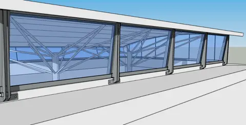
Glazed elements performance is evaluated by the debris penetration in the room/area and its level of human injury or lethality due to failed glazing fragment velocities (m/sec) and its horizontal trajectory (m) by usign e.g. HAZL/WINGARD. The corresponding Hazard Rating is defined in accordance with the American Society for Testing and Materials (ASTM) standard F1642.
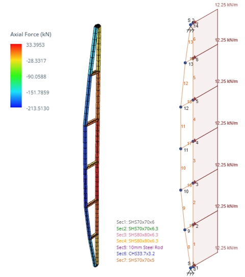
Structural components performance is evaluated by comparing the support rotations and member ductility, static and dynamic structural responses with SDOF (SBEDS), FE and CFD in accordance with UFC 3-340-02, Structures to Resist the Effects of Accidental Explosion and the U.S. Army Corps of Engineers Protective Design Center Technical Report PDC_TR-06-01.
Pressure–Impulse (P–I) diagrams are developed to quantify the dynamic response of Components across a range of loading combinations relative to predefined damage levels.
The corresponding Damage Level is defined in accordance with the United States Army Corps of Engineers publication PDC-TR-06-08 “Response limits for Antiterrorism Design“,
and ASCE ASCE 59-22: Blast Protection of Buildings.
For completeness and verification, the response of Components at the asymptotic impulse condition are also presented as a full SDOF time-history solution in to provide an independent check against the P–I diagram results.
Blast load calculation
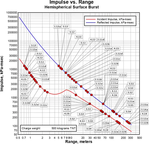
Using the Kingery-Bulmash equations (UFC 3-340-01) we can determine the standoff required to achieve a specific impulse as a function of standoff for a specific charge size.
VBIED, PBIED or IED refers to Improvised Explosive Device (IED) which is a descriptive term rather than specific explosive characteristics. It is important to mention that most forms of IED rarely produce a quality discharge such as industrial/military grade TNT. Nevertheless, the use of TNT equivalent charge sizes is widely used as a baseline for VBIED calculations.
The mathematical response analysis, based on the Reflected Impulse input, results in component response criteria on which can determine the building level of protection for each case. The building Level of Protection categories are defined in accordance with the United States Unified Facility Criteria (UFC) No. 4-010-01 DoD Minimum Antiterrorism Standards for Building as:
“Below Anti-terrorism standard“, “Very Low“, “Low“, “Medium” or “High“.
For each protection level defined, the corresponding expected structural response is given as a degree of Potential Overall Structural Damage.
UFC 3-340-01
Example diagram: 500kg TNT charge
Threat visualization
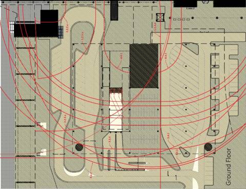
Vulnerability Mapping
The minimum standoff calculations that set the maximum allowable response level for each element based on its structural type (Primary, Secondary, Non-Structural) and geometrical adjustment based on site conditions, are used to map the vulnerable (risk) area for each threat scenario. Since there is often no way to determine the most severe locations for a VBIED detonation, this method provides a full unconditional site specific Vulnerability Analysis.
By visualizing the Risk Areas for each element – independently from its blast location – this analytical method will efficiently quantify the risk to the structure in a way that will practically assist in developing the most efficient counter measures for the risk.
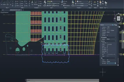
Proprietary Vulnerability Mapping
Example: plotted Risk Areas
Risk Mitigation Measures
Developing feasible Concept Mitigation Measures & Detail design & engineering
Where calculated performances of elements fail to achieve the required level of Protection, we propose feasible concept Mitigation Measures to minimize vulnerability.
Next, we perform vulnerability analyses for each of the proposed options in order to quantify the improved level of protection. Proposed retrofit options may include, for example:
a) Modifications to the site and/or the building structure;
b) Increased standoff distances, safety perimeters, and hostile vehicle mitigation option;
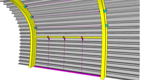
c) Retrofit of existing elements (structural or cladding) using physical means;
d) Protection from secondary threats such as fragmentation, fire, etc.;
Detail Design Calculations
In this stage we will provide detailed design calculations to provide sufficient architectural and engineering information for the project design team to integrate the detailed design of the physical mitigation measures into the existing building.
This may include the following information as required:
a) Performance specifications of the physical mitigation measures.
b) Location drawings of the physical mitigation measures.
c) Detailed site-specific engineering parameters for integration by the design team in the project drawings.
d) Performance specification for the physical mitigation measures.
Request for Quotation?
Installation
Our security products are shipped and installed worldwide. With highly experienced supervisors collaborating seamlessly with local installation teams, we ensure successful and certified installations every time.